How Connect Cables
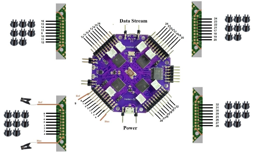
IronBCI-32 uses 34 electrode connections in total:
- 32 channel electrodes — placed on the scalp to measure biosignals
- 1 Reference electrode — clip electrode attached to one ear
- 1 Bias electrode — clip electrode attached to the other ear
All electrodes use a 2.54 mm pin pitch connector. Refer to the connection schematic above for the exact pin position of each electrode on the board headers.
Step 1 — Connect the Channel Electrodes
Connect the 32 channel electrodes to the numbered header pins on the IronBCI-32 board, following the schematic. Use wet (Ag/AgCl) electrodes for best signal quality. Place the electrodes on the scalp according to the international 10-20 system for consistent and reproducible electrode positioning. For a 32-channel setup, electrodes typically cover the full scalp including frontal, temporal, parietal, and occipital regions.
Step 2 — Connect the Reference Electrode
Attach a clip electrode to one ear. This provides a stable voltage reference for all 32 channels. Connect its cable to the REF pin on the board.
Step 3 — Connect the Bias Electrode
Attach a second clip electrode to the other ear. This actively drives a common-mode signal back into the body to cancel electromagnetic interference. Connect its cable to the BIAS pin on the board.
Step 4 - Confirm the right conenction