Electrodes & Pinout
Electrode connections
PiEEG-16 has two groups of 8 channels, one for each ADS1299 chip, plus a shared reference and bias.
| Input | Count | Electrode | Purpose |
|---|---|---|---|
| Channels 1–8 | 8 | Dry or wet Ag/AgCl, in the cap | Read by ADS1299 #1 |
| Channels 9–16 | 8 | Dry or wet Ag/AgCl, in the cap | Read by ADS1299 #2 |
| Reference | 1 | Ear clip on one earlobe | The common 0 µV point that all 16 channels are measured against |
| Bias | 1 | Ear clip on the other earlobe | Actively drives the body to cancel common-mode noise such as 50/60 Hz mains hum |
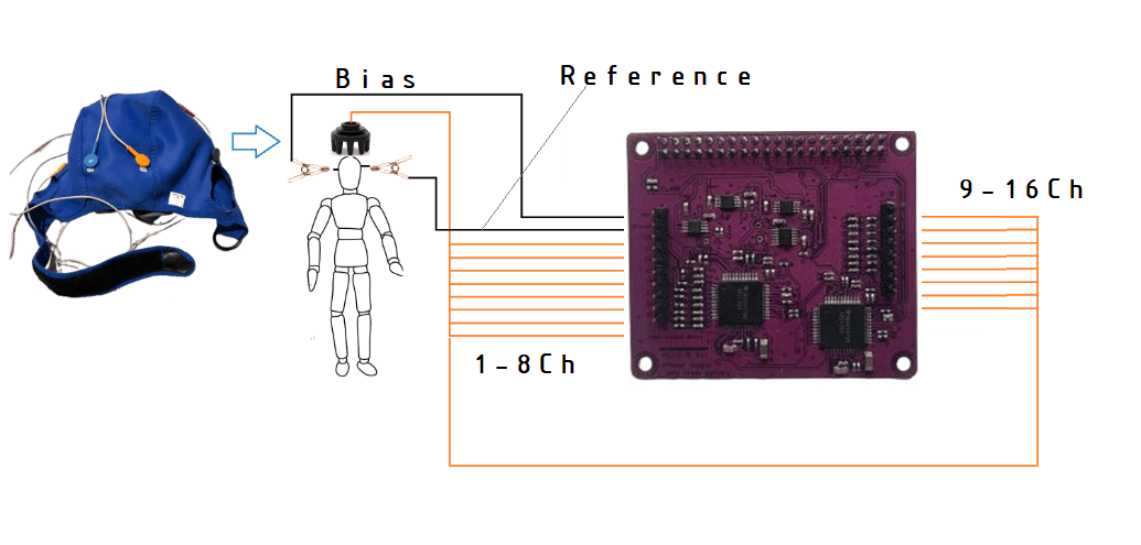
The electrode headers are standard 2.54 mm pin headers, so most EEG cables with 2.54 mm (0.1") female connectors fit. Check the pitch before using a third-party cap. See Cap.

The reference and bias clips matter most. A loose ear clip makes all 16 channels noisy at once. Clean the earlobes and make sure both clips sit firmly before you look at anything else.
Suggested montage
Place the electrodes on the 10-20 system. This layout covers the whole head. Channels 1–8 are the same as the PiEEG-8 default, so recordings from both boards can be compared.
| Channel | Position | Area | Channel | Position | Area | |
|---|---|---|---|---|---|---|
| 1 | Fp1 | Front left | 9 | F7 | Front left, side | |
| 2 | Fp2 | Front right | 10 | F8 | Front right, side | |
| 3 | C3 | Centre left | 11 | F3 | Front left | |
| 4 | C4 | Centre right | 12 | F4 | Front right | |
| 5 | P7 | Back left, side | 13 | T7 | Left temple | |
| 6 | P8 | Back right, side | 14 | T8 | Right temple | |
| 7 | O1 | Back left | 15 | P3 | Back left, top | |
| 8 | O2 | Back right | 16 | P4 | Back right, top |
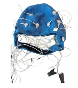
You can use any other positions. Just keep a note of which channel went where, because the software only knows channel numbers.
Fitting the cap
- Measure the head and pick the right cap size.
- Find Cz (halfway between nose and the back of the head, halfway between the ears) and align the cap with it.
- Dry electrodes: part the hair under each electrode so it touches the scalp.
- Wet electrodes: inject a small amount of conductive gel under each electrode and work it through the hair with the blunt syringe tip.
- Attach the ear clips to clean earlobes.
- Ask the person to sit still and relax the face and jaw.
With 16 electrodes, cable management matters. Bundle the leads together and keep them short and still. Moving cables show up as noise.
Raspberry Pi pinout
Both ADS1299 chips share the SPI0 bus. Each chip has its own chip-select line and its own data ready (DRDY) line.
| Header pin | Raspberry Pi GPIO | Signal | Chip |
|---|---|---|---|
| 19 | GPIO 10 | SPI0 MOSI | Both |
| 21 | GPIO 9 | SPI0 MISO (DOUT) | Both |
| 23 | GPIO 11 | SPI0 SCLK | Both |
| 24 | GPIO 8 | SPI0 CE0 (chip select) | ADS1299 #1 (channels 1–8) |
| 35 | GPIO 19 | Chip select, driven by software | ADS1299 #2 (channels 9–16) |
| 37 | GPIO 26 | DRDY 1 (data ready) | ADS1299 #1 |
| 33 | GPIO 13 | DRDY 2 (data ready) | ADS1299 #2 |
The shield also takes its power and ground from the header.
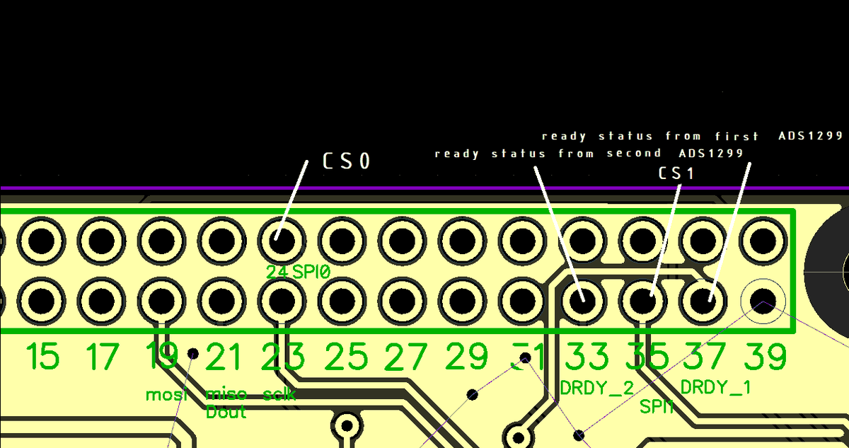
Each DRDY line goes low when its chip has a new sample (250 times per second). Software waits for DRDY 1 and reads chip 1, then waits for DRDY 2, pulls GPIO 19 low and reads chip 2. Details in Specification.