Specification
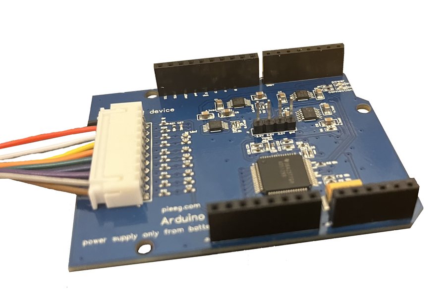
Hardware
| Channels | 8 biosignal inputs |
| Extra inputs | Reference (shared by all channels) and bias |
| Analog front end | Texas Instruments ADS1299 |
| Resolution | 24-bit, delta-sigma, all channels sampled at the same moment |
| Sample rate | 250 SPS as set by the sketch (the ADS1299 supports 250 SPS to 16 kSPS) |
| Gain | 1 as set by the sketch (the ADS1299 supports 1, 2, 4, 6, 8, 12, 24) |
| Reference voltage | 4.5 V internal |
| Internal noise | About 0.5 µV RMS per channel (measured, Signals & Datasets) |
| Signals | EEG, EMG, ECG |
| Electrodes | Dry or wet Ag/AgCl, 2.54 mm header |
| Host | Arduino UNO R4 WiFi |
| Interface | SPI (D13, D12, D11, chip select D10) and DRDY on D7 |
| Power | 5 V from a small power bank: up to 1 A, up to 1,000 mAh |
| Isolation | None. Battery operation is required. |
| Licence | Software and SDK: MIT |
SPI settings
| Setting | Value |
|---|---|
| Clock | 600 kHz |
| Mode | 1 (CPOL 0, CPHA 1) |
| Bit order | MSB first |
| Chip select | D10 |
Data format
Each sample is 27 bytes, read from the ADS1299 when DRDY (D7) goes low:
| Bytes | Content |
|---|---|
| 1–3 | ADS1299 status word |
| 4–6 | Channel 1 |
| … | … |
| 25–27 | Channel 8 |
Each channel is a 24-bit, big-endian, two's-complement value.
Over Wi-Fi, the sketch sends UDP packets of 1,350 bytes = 50 samples to your computer on port 13900. At 250 SPS that is 5 packets, or 6,750 bytes, per second.
Converting to microvolts
The conversion used by the PiEEG scripts:
raw = (b[0] << 16) | (b[1] << 8) | b[2]   # 3 bytes of one channel
if raw & 0x800000:                       # negative value
    raw -= 16777214
uV = raw * 4.5 / 16777215 * 1_000_000    # about 0.268 µV per count
Minimal Python receiver
import socket

UDP_IP, UDP_PORT = "192.168.1.241", 13900   # this computer's IP
sock = socket.socket(socket.AF_INET, socket.SOCK_DGRAM)
sock.bind((UDP_IP, UDP_PORT))

def to_uv(b):
    raw = (b[0] << 16) | (b[1] << 8) | b[2]
    if raw & 0x800000:
        raw -= 16777214
    return raw * 4.5 / 16777215 * 1e6

while True:
    packet, _ = sock.recvfrom(1350)
    for s in range(0, len(packet), 27):                  # 50 samples per packet
        sample = packet[s:s + 27]
        ch = [to_uv(sample[3 + 3*i: 6 + 3*i]) for i in range(8)]
        print([round(v, 1) for v in ch])
ADS1299 settings used by the sketch
Start-up: WAKEUP (0x02), STOP (0x0A), RESET (0x06), SDATAC (0x11), write the registers below, then RDATAC (0x10) and START (0x08).
| Address | Register | Value | Meaning |
|---|---|---|---|
0x01 | CONFIG1 | 0x96 | 250 SPS |
0x02 | CONFIG2 | 0xD4 | Internal test-signal settings (not used in normal mode) |
0x03 | CONFIG3 | 0xFF | Internal reference buffer on, internal bias reference, bias buffer on |
0x04 | LOFF | 0x00 | Lead-off detection off |
0x05–0x0C | CH1SET–CH8SET | 0x00 | Normal electrode input, gain 1 |
0x0D–0x11 | BIAS_SENS, LOFF_SENS, LOFF_FLIP | 0x00 | |
0x14 | GPIO | 0x80 | |
0x15 | MISC1 | 0x20 | Reference electrode shared by all channels (SRB1) |
0x17 | CONFIG4 | 0x00 | Continuous conversion |
Write a register with three bytes: [0x40 | address, 0x00, value].
Noise self-test: set every CHnSET to 0x01 (input shorted) in the sketch. The signal should stay within a few µV. See Noise elimination.