Specification
Everything you need to know about the hardware, plus the low-level details for writing your own driver.
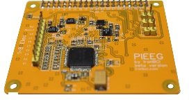
Hardware
| Channels | 8 single-ended biosignal inputs |
| Extra inputs | Reference (SRB1, common to all channels) and bias drive |
| Analog front end | Texas Instruments ADS1299 |
| Resolution | 24-bit, delta-sigma, all channels sampled at the same moment |
| Sample rate | 250 SPS as set by PiEEG software (the ADS1299 supports 250 SPS to 16 kSPS) |
| Gain | 1 as set by PiEEG software (ADS1299 supports 1, 2, 4, 6, 8, 12, 24) |
| Reference voltage | 4.5 V internal |
| Signals | EEG, EMG, ECG |
| Electrodes | Dry or wet Ag/AgCl |
| Electrode connector | 2.54 mm pin header |
| Status LED | On when the board is powered |
| Host | Raspberry Pi 4, Raspberry Pi 5 |
| Host connector | 40-pin GPIO header |
| Interface | SPI0, CE0, plus DRDY on GPIO 26 |
| Power | 5 V via the Raspberry Pi, from a battery (power bank) only |
| Isolation | None. Battery operation is required. |
| Licence | Software and SDK: MIT |
Software support
| Software | Device setting |
|---|---|
| PiEEG Server | --device pieeg8 |
| BrainFlow (opens in a new tab) | BoardIds.PIEEG_BOARD (56) |
| Python SDK (opens in a new tab) | 1.8_ch_Pi4.py, 1.8_ch_Pi5.py |
GPIO pins
| Header pin | GPIO | Signal |
|---|---|---|
| 19 | GPIO 10 | SPI0 MOSI |
| 21 | GPIO 9 | SPI0 MISO |
| 23 | GPIO 11 | SPI0 SCLK |
| 24 | GPIO 8 | SPI0 CE0 |
| 37 | GPIO 26 | DRDY (active low) |
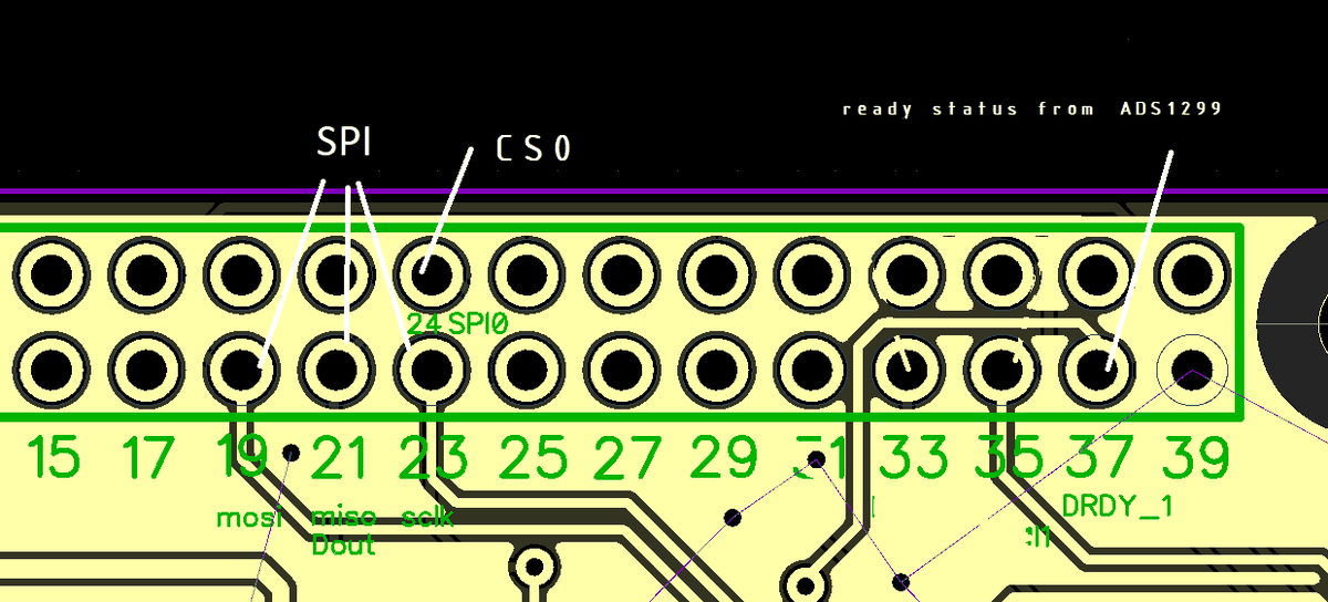
| Pi | GPIO chip for DRDY |
|---|---|
| Raspberry Pi 4 | /dev/gpiochip0 (or RPi.GPIO, board pin 37) |
| Raspberry Pi 5 | /dev/gpiochip4 (RP1). Check with gpiodetect if your OS version differs. |
SPI settings
| Setting | Value |
|---|---|
| Bus / device | /dev/spidev0.0 |
| Mode | 1 (CPOL 0, CPHA 1) |
| Bit order | MSB first |
| Word size | 8 bits |
| Clock | 600 kHz in the SDK scripts. PiEEG Server uses 4 MHz on Pi 4 and 2 MHz on Pi 5. |
Data frame
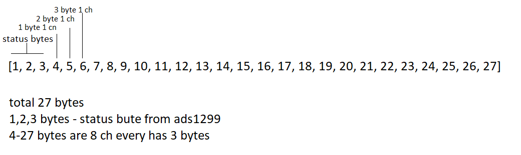
Each time DRDY goes low, read 27 bytes:
| Bytes | Content |
|---|---|
| 1–3 | ADS1299 status word (normally 0xC0 0x00 0x08) |
| 4–6 | Channel 1 |
| 7–9 | Channel 2 |
| … | … |
| 25–27 | Channel 8 |
Each channel is a 24-bit, big-endian, two's-complement value. At 250 SPS you get 250 frames per second.
Converting to microvolts
This is the conversion used by the PiEEG SDK scripts and PiEEG Server:
raw = (b[0] << 16) | (b[1] << 8) | b[2]   # 3 bytes of one channel
if raw & 0x800000:                       # negative value
    raw -= 16777214
uV = raw * 4.5 / 16777215 * 1_000_000    # about 0.268 µV per count
Reading a sample
import spidev
spi = spidev.SpiDev()
spi.open(0, 0)                 # SPI0, CE0
spi.max_speed_hz = 600000
spi.mode = 0b01

# ... configure the ADS1299 (see below), then for every sample:
# 1. wait until DRDY (GPIO 26) goes from high to low
# 2. read one frame
frame = spi.readbytes(27)
ADS1299 commands
| Command | Code |
|---|---|
| WAKEUP | 0x02 |
| RESET | 0x06 |
| START | 0x08 |
| STOP | 0x0A |
| RDATAC (read data continuously) | 0x10 |
| SDATAC (stop continuous read) | 0x11 |
Write a register with three bytes: [0x40 | address, 0x00, value]. Read one with [0x20 | address, 0x00, 0x00].
Default register settings
Start-up sequence used by PiEEG software: WAKEUP, STOP, RESET, SDATAC, write the registers below, then RDATAC and START.
| Address | Register | Value | Meaning |
|---|---|---|---|
0x01 | CONFIG1 | 0x96 | 250 SPS |
0x02 | CONFIG2 | 0xD4 | Internal test-signal settings (not used in normal mode) |
0x03 | CONFIG3 | 0xFF | Internal reference buffer on, internal bias reference, bias buffer on |
0x04 | LOFF | 0x00 | Lead-off detection off |
0x05–0x0C | CH1SET–CH8SET | 0x00 | Normal electrode input, gain 1 |
0x0D | BIAS_SENSP | 0x00 | |
0x0E | BIAS_SENSN | 0x00 | |
0x0F | LOFF_SENSP | 0x00 | |
0x10 | LOFF_SENSN | 0x00 | |
0x11 | LOFF_FLIP | 0x00 | |
0x14 | GPIO | 0x80 | |
0x15 | MISC1 | 0x20 | SRB1 on: the reference electrode is shared by all channels |
0x17 | CONFIG4 | 0x00 | Continuous conversion |
Noise self-test: set every CHnSET to 0x01 (input shorted). The signal should stay within a few µV. If it does, the board is fine and any noise comes from the cables, electrodes or surroundings. See Noise elimination.
Changing CONFIG1–3 changes the sample rate or reference. PiEEG Server and BrainFlow expect 250 SPS.