Specification
Everything you need to know about the hardware, plus the serial data format for writing your own software.
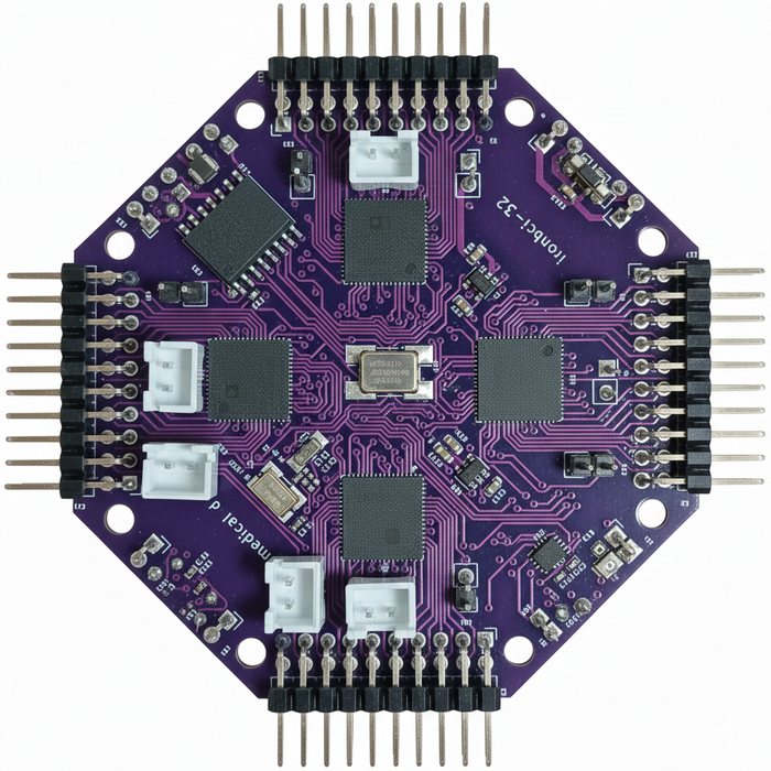
Hardware
| Channels | 32 biosignal inputs (4 groups of 8) |
| Extra inputs | Reference and bias (on the CH 1–8 header) |
| Analog front end | 4 × Analog Devices AD7771, 8 channels each |
| Resolution | 24-bit |
| Noise | Ultra-low-noise sources and references, measured below 0.22 µV (from the IronBCI-32 repository) |
| Sample rate | About 500 SPS, fixed by the firmware (BrainFlow's board description lists 512 Hz) |
| Microcontroller | STM32H743 (Arm Cortex-M7), with real-time pre-processing |
| Signals | EEG, EMG, ECG, EOG |
| Electrodes | Dry or wet Ag/AgCl |
| Electrode connectors | 4 × 2.54 mm double-row headers |
| Data port | Micro USB, USB CDC virtual serial port |
| Power port | Micro USB, 5 V from a USB battery only |
| Programming | SWD header (GND, RST, SWDIO, SWCLK) for an ST-Link |
| PCB | 70 × 70 mm, 4 layers, 1.6 mm, FR4 |
| Isolation | None. Battery operation of the board and the laptop is required. |
| Hardware files | KiCad schematic and Gerber files in the repository (opens in a new tab) |
Software support
| Software | Setting |
|---|---|
| BrainFlow (opens in a new tab) | BoardIds.IRONBCI_32_BOARD (65), serial_port |
| PiEEG Server | --device ironbci32 --serial-port … (needs pieeg-server[ironbci32]) |
| PiEEG Cloud | PiEEG Devices → IronBCI-32 (Web Serial) |
| JavaScript SDK | connectSerial({ device: 'ironbci-32' }) (default for Web Serial) |
Serial data format
| Port | USB CDC ACM (virtual COM port) |
| Baud rate | 921,600 |
| Start | Streams as soon as the board is powered. No start command. |
| Frame rate | One frame per sample, about 500 per second |
Frame layout
| Bytes | Content |
|---|---|
| 1 | 0xA0 start marker |
| 2 | Sample counter (0–255, wraps) |
| 3–98 | 32 channels × 3 bytes, 24-bit big-endian two's complement |
| 99 … n−1 | Status and padding bytes (length depends on the firmware) |
| n | 0xC0 end marker |
Frames observed on current firmware are 107 bytes long. Robust parsers find the frame length from the distance between consecutive 0xC0 0xA0 pairs instead of assuming a fixed size.
Converting to microvolts
This is the conversion used by PiEEG Server and BrainFlow's FreeEEG decoder (2.5 V reference, gain 8):
raw = (b[0] << 16) | (b[1] << 8) | b[2]   # 3 bytes of one channel
if raw & 0x800000:                       # negative value
    raw -= 1 << 24
uV = raw * 2.5 / 8388607 / 8 * 1_000_000 # about 0.03725 µV per count
Raw values carry a large DC offset (tens of thousands of µV) from the electrode contact. That is normal. Apply a high-pass or band-pass filter before looking at EEG.
Minimal reader
import serial

PORT = "COM3"                       # or "/dev/ttyACM0"
FRAME = 107                         # check with the 0xC0 0xA0 method if unsure

with serial.Serial(PORT, 921600, timeout=1) as s:
    buf = bytearray()
    while True:
        buf += s.read(1024)
        i = buf.find(b"\xA0")
        while i >= 0 and len(buf) - i >= FRAME:
            f = buf[i:i + FRAME]
            if f[-1] == 0xC0:
                ch = []
                for c in range(32):
                    b = f[2 + 3*c: 5 + 3*c]
                    raw = (b[0] << 16) | (b[1] << 8) | b[2]
                    if raw & 0x800000:
                        raw -= 1 << 24
                    ch.append(raw * 2.5 / 8388607 / 8 * 1e6)
                print(f[1], [round(v, 1) for v in ch[:4]], "...")
                buf = buf[i + FRAME:]
            else:
                buf = buf[i + 1:]
            i = buf.find(b"\xA0")
For real projects, use BrainFlow or PiEEG Server, which handle frame detection and errors for you.